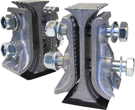
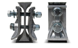
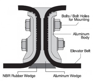
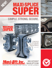
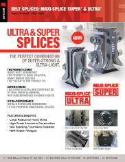
 Named for its superior design, performance and size, the MAXI-SPLICE SUPER (along with its counterpart the MAXI-SPLICE ULTRA) defines the next generation of elevator belt splices. The unique design embraces our MAXI-SPLICE three piece construction, with the addition of an NBR rubber wedge to protect against belt wear for long life. Designed with a larger radius for gentle belt turns, the larger SUPER has two bolts for additional clamping force and plate friction.
FEATURES / BENEFITS
- High Grade, Lightweight Aluminum Construction
- NBR Rubber Wedge Protects Backside of Belt
- Template Tape Included
- Weight: 4.8 lbs. each
- Two Bolt Design
- 3/4” x 5” and 3/4” x 5 -1/2” Hex Head Bolts
- Usable on Belts Rated 800-1200 PIW tensile.
APPLICATIONS
- High Capacity Elevators
- Export Facilities
- Processing Plants
- River Terminals
- Wide Bucket Elevators
- Multiple Row Bucket Elevators
Technical Info
 Each Splice accommodates 3” of belt width
- Grade 5 Bolts – 3/4” Diameter
- Rubberized wedge section is oil resistant, suitable for use up to 176° F / 80° C (Use aluminum wedge for higher temperatures)
- Use Super template tape and Power Punch to install (Torque 150 ft. / lbs.)
- Weight: 4.8 lbs.
- Length: 6-3/4 in.
- Width: 3 in.
*Patent Pending
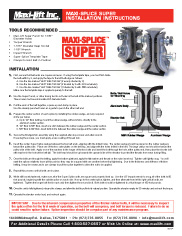
Installation (Download PDF Instructions)
- First, ensure that belt ends are square and even. If using the template tape, you must first divide the belt width by 3, and apply the tape to the left belt edge as follows:
A. Use the line marked “LEFT BELT EDGE” (if evenly divided by 3)
B. Use the line marked “LEFT BELT EDGE” (if divided by 3 with .333 remainder)
C. Use the line marked “LEFT BELT EDGE “(if divided by 3 with .666 remainder)
Make sure the template tape is applied squarely to the belt. - Use the Super Punch, or other boring tool to cut holes in the belt at the marked positions. These holes must accommodate 3/4” diameter bolts.
- Pull the ends of the belt together, square up and clamp in place. Use the already punched holes as a guide to punch the other belt end.
- Prepare the center section of each splice by installing the rubber wedge, and any required shims per below.
A. Up to 1/2” thick belting, mount the rubber wedge, without shims, directly to the aluminum center section.
B. 1/2” thick to 5/8” thick, insert one shim between the rubber wedge and the center section.
C. 5/8” thick to 3/4” thick, insert both shims between the rubber wedge and the center section. - Secure the Wedge/shim assembly using the supplied allen key screws and allen wrench. If reusing the screws, you must apply a new coating of thread lock.
- Insert the center Super Splice wedge between the two belt ends, aligning with the drilled holes. The center wedge should be placed so the rubber wedge is toward the pulley side. Place one of the two outer plates on the belt top, and align with the holes drilled in the belt. The large radius end should be toward the pulley side of the belt. Apply one of the washers to the longer of the two bolts and insert the bolt through the hole at the pulley end, then place the shorter bolt with washer in the hole at the belt tail. The bolt head should be up towards the upward side of the elevator to protect the threads from wear during filling.
- Once the bolts are through the belting, apply the bottom plate and apply the flat washer and thread on the nylon insert nut. Tighten until lightly snug. You will want the splices relatively loose at this point so they may be squared with one another before final tightening. Due to the thickness and stiffness of thicker belting, it may be necessary to use clamps to pull the splice together to allow the nut to be applied.
- Repeat this process until all units are in place.
- While still loosely fastened, make sure all of the Super Splice units are square and properly lined up. Use the 1/2” impact wrench to snug all of the bolts to 50 foot pounds, beginning with the outside splice on each side. Now go to the center splice, tighten, and then alternate from left to right until all units are tightened. Tighten the longer bolt first in each unit, then tighten the second bolt. Both bolts should be tightened to a final torque of 150 foot pounds.
- Once the unit is fully tightened, release the clamps and allow the belt to pull into its natural position. Operate the elevator empty for 30 minutes and recheck the torque.
- Operate the elevator under load, and recheck again.
DISCLAIMER: Failure to properly select or install any belt splice can result in splice failure and cause equipment and property failure which may also result in bodily injury or death. Proper procedures for installation must be strictly followed. SEE FULL DISCLAIMER ON WWW.MAXILIFT.COM
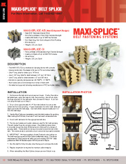
View/Print the Comparison Chart (PDF)
Belt Splice Technical Data Sheet
| PART DETAILS | Product | MAXI-SPLICE | MAXI-SPLICE | MAXI-SPLICE | MAXI-SPLICE | MAXI-SPLICE |
| Brand | CI | AB | ULTRA | SUPER | TITAN | |
| Part No | CI5 | AB5 | ULTRA5 | SUPER5 | TITAN | |
| SPLICE CONSTRUCTION | Color | Silver | Manganese Bronze | Silver | Silver | Silver |
| Construction | 3 Piece Mechanical Clamping Device | 3 Piece Mechanical Clamping Device | 3 Piece Mechanical Clamping Device with NBR (Nitrile) Rubber Wedge | 3 Piece Mechanical Clamping Device with NBR (Nitrile) Rubber Wedge | 3 Piece Mechanical Clamping Device with HNBR Rubber Wedge | |
| Metal Material | Galvanized Cast Iron | Manganese Bronze | Aluminum | Aluminum | Aluminum | |
| Metal Description | Ferrous Cast Iron | Non-Ferrous Bronze | High Grade, Lightweight Aluminum | High Grade, Lightweight Aluminum | High Grade, Lightweight Aluminum | |
| Rubber Material | None | None | Replaceable NBR Rubber Wedge | Replaceable NBR Rubber Wedge | Replaceable HNBR Rubber Wedge | |
| SPLICE SPECIFICATIONS | Weight (lbs.) | 2.6 | 2.9 | 1.93 | 4.8 | Per Application |
| Length | 3″ | 3″ | 4-1/2″ | 6-1/4″ | 6″ | |
| Width | 2″ | 2″ | 2-1/2″ | 3″ | Per Application | |
| PIW Rated | Up to 600 PIW Tensile | Up to 800 PIW Tensile | Up to 800 PIW Tensile | 800-1200 PIW Tensile | Over 1200 PIW | |
| Recommended Belt Thickness | 1/4″ to 5/8″ | 1/4″ to 5/8″ | 1/4″ to 5/8″ | 3/8″ to 3/4″ | Per Application | |
| BOLT SPECIFICATIONS | No of Bolts | 1 | 1 | 1 | 2 | Per Application |
| Bolt Grade | Grade 5 Hex Head Bolt | Grade 5 Hex Head Bolt | Grade 5 Hex Head Bolt | Grade 5 Hex Head Bolt | M16 10.9 Hex Head Bolt | |
| Bolt Diameter (Inches) | 1/2″ | 9/16″ | 5/8″ | 3/4″ | Per Application | |
| Bolt Length (Inches) | 5″ | 5″ | 4-1/2″ | 5″ and 5-1/2″ | Per Application | |
| Washers | Yes | Yes | Yes | Yes | Yes | |
| Nuts | Nylock | Nylock | Nylock | Nylock | Oval Lock Nut | |
| Recommended Torque * | 75 ft./lbs | 100 ft./lbs. | 125 ft./lbs. | 150 ft./lbs. | Per Application | |
| Template Tape Included | Yes | Yes | Yes | Yes | Requires Special Template | |
| SHIMS | Required Shims Per Belt Thickness | N/A | N/A | Under 5/16” – No Shims 5/16” to 3/8” – 1 Shim 3/8” to 1/2” – 2 Shims | Under 1/2” – No Shims 1/2” to 5/8” – 1 Shim 5/8” to 3/4” – 2 Shims | N/A |
| TEMPERATURE RATINGS | Max. Operating Temps | 600° F / 350° C | 500° F / 260° C | 200° F / 93° C (NBR Rubber Wedge Limiting Factor) – Alternative Wedges Available for Higher Temperatures | 200° F / 93° C (NBR Rubber Wedge Limiting Factor) – Alternative Wedges Available for Higher Temperatures | 320° F / 160° C (HNBR Hydrogenated Nitrile Butadiene Rubber Wedge Limiting Factor) |
| Nylock Nut Max. Temp | 250° F | 250° F | 250° F | 250° F | 320° F | |
| MINIMUM HEAD PULLEY DIAMETER | Agricultural (High Speed) ** | 12″ | 12″ | 24″ | 30″ | 48″ |
| Industrial (Centrifugal/Gravity) | 12″ | 12″ | 20″ | 36″ | 48″ | |
| BUCKET PROJECTION | Minimum Recommended | 4″ | 4″ | 5″ | 7″ | 8″ |
| FEATURES/ BENEFITS | Strong, Standard, Mechanical Splice | Non-Sparking, Non-Corroding, Non-Rusting | Non-Sparking, Non-Corroding, Non-Rusting, Longer Belt Life | Non-Sparking, Non-Corroding, Non-Rusting, Longer Belt Life | Non-Sparking, Non-Corroding, Non-Rusting, Longer Belt Life |
WARNING: DO NOT USE ANY MAXI-SPLICE ON MANLIFTS!
Please read all instructions before installing any Maxi-Splice product. Instructions can be found at maxilift.com. Failure to follow installation instructions may result in splice failure. As with any belt splice, continuous, regular inspections are required or failure can occur.
Never mix Maxi-Splice products on a single installation. Reduced or uneven clamping pressure may occur compromising splice integrity and could result in splice failure.
Maxi-Lift neither solicits nor recommends the use of any Maxi-Splice belt clamp for splicing man-lift belts. Maxi-Splices were neither designed for nor tested for this purpose. Any installation of a Maxi-Splice product for this purpose may result in splice failure causing serious bodily harm or even death. Do not use on steel cable belts.
Do not reuse nylon insert lock nuts when reinstalling Maxi-Splices. Please use new nylock nuts for reinstallation. Replacements are available from Maxi-Lift.
For applications exceeding 250° F, nylon insert lock nuts may not be used, as this temperature range exceeds the manufacturer’s threshold for nylon integrity. Compression locking nuts should be utilized instead.
While the AB and CI Maxi-Splice may be used on wing pulleys, they may contribute to wear on the backside of the belt at the splice. It is the user’s responsibility to inspect the splice at regular maintenance intervals to prevent failure. Noise may also be heard as the splice contacts the wings of the pulley.

Sonya Fisher
Inside Sales
Eivind Flores
Inside/International Sales
Matt Porter
Technical Sales Specialist
Drew Lassiter
Business Development Specialist
Dean Wedekind
Technical Sales Specialist
Adriel Sastre
Inside Sales
Lesly Solorzano
Inside Sales