-1.png?width=240&height=124&name=image%2012%20(1)-1.png)
-1.png?width=240&height=124&name=image%2012%20(2)-1.png)
-1.png?width=120&height=62&name=image%2012%20(3)-1.png)
-1.png?width=120&height=62&name=image%2012%20(4)-1.png)
-1.png?width=240&height=124&name=image%2012%20(5)-1.png)
.png?width=240&height=124&name=image%2012%20(6).png)
.png?width=240&height=124&name=image%2012%20(7).png)
.png?width=240&height=124&name=image%2012%20(8).png)
.png?width=240&height=124&name=image%2012%20(14).png)
-1.png?width=240&height=124&name=image%2012%20(9)-1.png)
-1.png?width=240&height=124&name=image%2012%20(10)-1.png)
.png?width=240&height=152&name=image%2029%20(3).png)
.png?width=240&height=124&name=image%2012%20(11).png)
.png?width=240&height=124&name=image%2012%20(12).png)
.png?width=240&height=124&name=image%2012%20(13).png)
.png?width=315&height=258&name=image%2046%20(1).png)


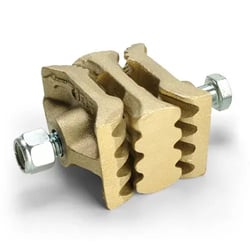
Maxi-Splice AB
- Non-ferrous metal of very high tensile strength
- Usable on belts up to 800 PIW tensile
- Non-sparking, non-corroding and non-rusting
- Bronze color
- Weight: 2.9 lbs. each
- Maximum operating temperature: 500°F
- Recommended belt thickness: 1/4″ to 5/8″
- 9/16” x 5” Grade 5 Hex Head Bolts
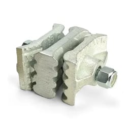
Maxi-Splice CI
- Ferrous metal of moderately high tensile strength
- Usable on belts of up to 600 PIW tensile
- Silver color
- Weight: 2.6 lbs. each
- Maximum operating temperature: 600°F
- Recommended belt thickness: 1/4″ to 5/8″
- 1/2” x 5” Grade 5 Hex Head Bolts
.png?width=145&height=120&name=image%2037%20(2).png)


Installation Instructions:
Installation Instructions – English (PDF) | Installation Instructions – Spanish (PDF)
- First ensure the belt ends are square and even. If using the splice template tape, apply the tape to mark the punching. Be sure to apply the tape squarely on the belt ends; then proceed to Step 4. If you are not using the tape, go to Step 2.
- Draw a line approximately 4-1/4″ from the belt end to use as the center line for hole punching. Proper installation for even width belts will begin just inside the belt edge. Odd belt widths require installation 1/2″ from the belt edge.
- Use the Maxi-Splice as a template to mark the hole locations for punching. After marking the first hole, move over 2″ and mark each consecutive hole.
- If available, use a Maxi-Lift Power Punch to punch holes in both belt ends. Holes should be sized for the appropriate bolt.
- The two end plates and center plate are used for firm belt gripping. The end plates have two gripping areas – the slotted gripping area is mounted toward the face of the belt and is followed by a series of gripping teeth. These teeth are always mounted toward the tail of the belt. The center plate is symmetrical and cannot be improperly installed.
- IMPORTANT: We have supplied a Grade 5 bolt and nylon locking nut. The bolts must be torqued for Maxi-Splice to effectively clamp. The torque requirement is 75 foot pounds for belts up to and including 600 PIW – belts greater than 600 PIW tensile require 100 foot pounds of torque.
- Run the belt for thirty minutes; stop the leg and re-torque the bolts.
- When reinstalling the Maxi-Splice always use new Nylock nuts.


As with any belt splice, after installation, continued inspection of the total installation is required or failure can occur.
Buyer is required to understand the instructions on the box are an abbreviated version; so buyer must obtain and fully understand the entire contents of our 4-page splice instruction guide before any installation occurs. If the 4-page instruction guide is not in the box, please check our website, otherwise it is the buyer’s responsibility to seek a copy from a company representative.
Maxi-splice is a mechanical splice device for use on most elevator belts (PVC and rubber). To accommodate various PIW belt tension ratings, Maxi-splice is available in two different metals. The Maxi-Splice “CI” is ferrous metal of moderately high tensile strength and can be used on belts up to 600 PIW. The Maxi-Splice “AB” is a non-ferrous metal of very high tensile and shear strength. The Maxi-Splice “AB” does not rust or corrode and is non-sparking. Maxi-Splice “CI” and Maxi-Splice “AB” are identical in appearance with the exception that the “AB” Maxi-Splice exhibits a bronze color. The CI and AB should never be intermixed, as reduction in clamping power may occur.
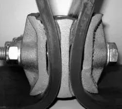
Each splice unit is made of three pieces. Two are identical outside plates; the third is a center plate with an elongated center hole. The outside plates and the center plate are “mating” parts with peaks and valleys opposite of each other for firm gripping.
The outside plates have two different gripping areas. The ribbed gripping area is mounted towards the face of the belt. The opposite end has a series of both longitudinal and axial “teeth.” The teeth are always mounted at the tail of the belt; they too have opposite peaks and valleys in the center plate for firm holding. The center plate is symmetrical and cannot be improperly installed around its elongated center hole.
The splice functions by using the tension supplied by the belting. This tension on the belt ends pulls the outer plates apart, and forces gripping pressure towards the teeth on the splice unit. The greater the belt tension, the more pressure is exerted on the gripping teeth at the forward end of the splice. The splice is held together by a ½” diameter, grade 5 bolt. The length of the bolt varies depending on belt thickness. If for any reason bolt replacement ever occurs, a grade 5 or better bolt must be used, with a nylon insert locking nut.
The clamping, holding force of the splice can only be facilitated after the grade 5 bolt is torqued during installation. Minimum torque of 75ft. lbs is required on the Maxi-Splice “CI.” A 100ft. lbs torque minimum is required on the Maxi-Splice “AB.” A torque wrench is required for proper installation. After installation is complete the belt must be run under load, for 30 minutes, then, each bolt must be re-torqued.
Each Maxi-Splice set will connect approximately 2″ of belt width. On a 36″ wide belt for example, 18 Maxi-Splice sets are required. See the Maxi-Splice installation sheet for proper use of the template tape or for placement and belt punching suggestions.
The Maxi-Splice has been tested and approved by leading manufacturers of both PVC and rubber elevator belts.
Buckets, Belts,
and Bundles
Need a catalog to flip through or more than a link to share? We can send you a catalog.

Buckets, Belts,
and Bundles
Need a catalog to flip through or more than a link
to share? We can send you a catalog.