-1.png?width=240&height=124&name=image%2012%20(1)-1.png)
-1.png?width=240&height=124&name=image%2012%20(2)-1.png)
-1.png?width=120&height=62&name=image%2012%20(3)-1.png)
-1.png?width=120&height=62&name=image%2012%20(4)-1.png)
-1.png?width=240&height=124&name=image%2012%20(5)-1.png)
.png?width=240&height=124&name=image%2012%20(6).png)
.png?width=240&height=124&name=image%2012%20(7).png)
.png?width=240&height=124&name=image%2012%20(8).png)
.png?width=240&height=124&name=image%2012%20(14).png)
-1.png?width=240&height=124&name=image%2012%20(9)-1.png)
-1.png?width=240&height=124&name=image%2012%20(10)-1.png)
.png?width=240&height=152&name=image%2029%20(3).png)
.png?width=240&height=124&name=image%2012%20(11).png)
.png?width=240&height=124&name=image%2012%20(12).png)
.png?width=240&height=124&name=image%2012%20(13).png)
.png?width=315&height=258&name=image%2046%20(1).png)


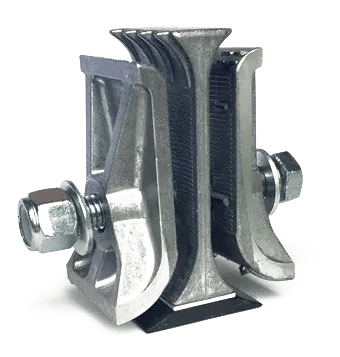
Product Summary
The ULTRA features all the advantages of the SUPER splice, but with a smaller frame and a single bolt design. Designed for belts up to 800 PIW, the ULTRA also features the MAXI-SPLICE three piece construction and NBR rubber wedge for protection against belt wear. Like the SUPER, the ULTRA is designed with a larger radius for gentle belt turns.
FEATURES / BENEFITS
- High Grade, Lightweight Aluminum Construction
- NBR Rubber Wedge Protects Backside of Belt
- Template Tape Included
- Weight: 1.93 lbs. each
- 5/8″ x 4 1/2″ Hex Head Bolt
- Rated for belts up to 800 PIW
APPLICATIONS
- High Capacity Elevators
- Export Facilities
- Processing Plants
- River Terminals
- Wide Bucket Elevators
- Multiple Row Bucket Elevators
Comparison Chart
.png?width=145&height=120&name=image%2037%20(2).png)


Part Details
Product
MAXI-SPLICE
MAXI-SPLICE
MAXI-SPLICE
MAXI-SPLICE
MAXI-SPLICE
Brand
CI
AB
ULTRA
SUPER
TITAN
Part No
CI5
AB5
ULTRA5
SUPER5
TITAN
SPLICE CONSTRUCTION
Color
Silver
Manganese Bronze
Silver
Silver
Silver
Construction
3 Piece Mechanical Clamping Device
3 Piece Mechanical Clamping Device
3 Piece Mechanical Clamping Device with NBR (Nitrile) Rubber Wedge
3 Piece Mechanical Clamping Device with NBR (Nitrile) Rubber Wedge
3 Piece Mechanical Clamping Device with HNBR Rubber Wedge
Metal Material
Galvanized Cast Iron
Manganese Bronze
Aluminum
Aluminum
Aluminum
Rubber Material
None
None
Replaceable NBR Rubber Wedge
Replaceable NBR Rubber Wedge
Replaceable HNBR Rubber Wedge
SPLICE SPECIFICATIONS
Weight (lbs.)
2.6
2.9
1.93
4.8
Per Application
Length
3″
3″
4-1/2″
6-1/4″
6″
Width
2″
2″
2-1/2″
3″
Per Application
PIW Rated
Up to 600 PIW Tensile
Up to 800 PIW Tensile
Up to 800 PIW Tensile
800-1200 PIW Tensile
Over 1200 PIW
Recommended Belt Thickness
1/4″ to 5/8″
1/4″ to 5/8″
1/4″ to 5/8″
3/8″ to 3/4″
Per Application
BOLT SPECIFICATIONS
No of Bolts
1
1
1
2
Per Application
Bolt Grade
Grade 5 Hex Head Bolt
Grade 5 Hex Head Bolt
Grade 5 Hex Head Bolt
Grade 5 Hex Head Bolt
M16 10.9 Hex Head Bolt
Bolt Diameter (Inches)
1/2″
9/16″
5/8″
3/4″
Per Application
Bolt Length (Inches)
5″
5″
4-1/2″
5″ and 5-1/2″
Per Application
Washers
Yes
Yes
Yes
Yes
Yes
Nuts
Nylock
Nylock
Nylock
Nylock
Oval Lock Nut
Recommended Torque *
75 ft./lbs
100 ft./lbs.
125 ft./lbs.
150 ft./lbs.
Per Application
Template Tape Included
Yes
Yes
Yes
Yes
Requires Special Template
SHIMS
Required Shims Per Belt Thickness
N/A
N/A
Under 5/16” – No Shims 5/16” to 3/8” – 1 Shim 3/8” to 1/2” – 2 Shims
Under 1/2” – No Shims 1/2” to 5/8” – 1 Shim 5/8” to 3/4” – 2 Shims
N/A
TEMPERATURE RATINGS
Max. Operating Temps
600° F / 350° C
500° F / 260° C
200° F / 93° C (NBR Rubber Wedge Limiting Factor) – Alternative Wedges Available for Higher Temperatures
200° F / 93° C (NBR Rubber Wedge Limiting Factor) – Alternative Wedges Available for Higher Temperatures
320° F / 160° C (HNBR Hydrogenated Nitrile Butadiene Rubber Wedge Limiting Factor)
Nylock Nut Max. Temp
250° F
250° F
250° F
250° F
320° F
MINIMUM HEAD PULLEY DIAMETER
Agricultural (High Speed) **
12″
12″
24″
30″
48″
Industrial (Centrifugal/Gravity)
12″
12″
20″
36″
48″
BUCKET PROJECTION
Minimum Recommended
4″
4″
5″
7″
8″
FEATURES/ BENEFITS
Strong, Standard, Mechanical Splice
Non-Sparking, Non-Corroding, Non-Rusting
Non-Sparking, Non-Corroding, Non-Rusting, Longer Belt Life
Non-Sparking, Non-Corroding, Non-Rusting, Longer Belt Life
Non-Sparking, Non-Corroding, Non-Rusting, Longer Belt Life


Buckets, Belts,
and Bundles
Need a catalog to flip through or more than a link to share? We can send you a catalog.

Buckets, Belts,
and Bundles
Need a catalog to flip through or more than a link
to share? We can send you a catalog.